meta data for this page
- en
Active Cooling of Acoustics Box
Calculations for peltier elements
Thermal resistance
The thermal resistance of an object determines how well heat flows through it. Objects with a high thermal resistance act as a barrier for heat. When heat is trying to dissipate, it won't be able to dissipate through objects with a high thermal resistance as easily as through objects with a low thermal resistance. If there is a path with a low thermal resistance, the heat will dissipate along this path. If the heat has to dissipate along a path with high thermal resistance, the heat will build up before the object acting as a bottleneck, causing the object to heat up. The thermal resistance describes how much the object heats up depending on the thermal power flowing.
\( R_{th} \): absolute thermal resistance [\(K/W\)]
Resistances connected in series:
\( R_{th,total} = R_{th,1} + R_{th,2} + R_{th,3} + \dots \)
Resistances connected in parallel:
\( \frac{1}{R_{th,total}} = \frac{1}{R_{th,1}} + \frac{1}{R_{th,2}} + \frac{1}{R_{th,3}} + \dots \)
\(L\): absolute heat conductivity [\(W/K\)]
\(L = \frac{1}{R_{th}} \)
Thermal resistance of a cylinder
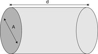
The thermal resistance of a cylinder like this can be calculated easily as long as the heat flows along d and the contact area A on either side is equal to the circle area of the cylinder.
\( \rho_{th} \): specific thermal resistance [\(\frac{K \cdot m}{W}\)]
\( A \): contact area on either side [\( m^{2} \)]
\( d \): length of cylinder [\(m\)]
\[ R_{th} = \frac{\rho_{th} \cdot d}{A} \]
\( \lambda \): specific thermal conductivity [\(\frac{W}{K \cdot m}\)]
\[ \lambda = \frac{1}{\rho_{th}}, \quad R_{th} = \frac{d}{\lambda \cdot A} \]
This formula is also applicable to any other parallelepipeds as long as the criteria given above apply.
Approximations for different contact areas
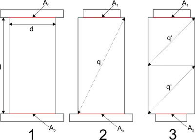
In case the contact area does have the same size as the base area of the parallelepiped (1), the formulas from above can be used. If this isn't the case, there are two other cases to distinguish between: The contact area is different from the base area on one side (2) or on both sides (3).
In case of (2) an approximation to the thermal resistance can be made by using following formulas:
\( R = \frac{l}{\lambda A} \) with \( A = \left( 1 - \frac{l}{q} \right) A_{1} + \frac{l}{q} A_{0} \) and \( q = \sqrt{l^{2} + d^{2}} \)
Case (3) can be treated as to cases of (2) back to back:
\( R = \frac{l}{\lambda A} \) with \( A = \left( 1 - \frac{l}{2q^{\prime}} \right) \frac{A_{1} + A_{2}}{2} + \frac{l}{2q^{\prime}} A_{0} \) and \( q^{\prime} = \sqrt{\frac{1}{4} l^{2} + d^{2}} \)
Approximation for shapes of changing cross sectional area
If the cross sectional area of an object is not constant, you can calculate the thermal resistance by integrating over the length of the object.
\[ R_{th} = \int_{x = 0}^{l} \frac{dx}{\lambda A(x)} \]
Approximation for more complex shapes
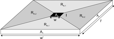
There are more complex shapes like this as well. In this case the heat transfer takes place from the black square with contact Area \(A_{0}\) in the middle of the plate to the side faces with contact Area \(A_{1}\). To calculate an approximation of the overall thermal resistance, the plate can be divided into smaller parts of which the thermal resistance can be calculated more easily. The thermal resistances can be then added together depending on how they are connected (in series/parallel).
Specific thermal conductivities for different materials
Some common materials:
| Material | Specific thermal conductivity [W/(K*m)] | Source(s) |
|---|---|---|
| Aluminum | 235 / 237 | Wolfram Alpha, Wikipedia |
| Ceramics | Median 1 | Wolfram Alpha |
| Copper | 400 / 401 | Wolfram Alpha, Wikipedia |
| Fused silica | 1.4 | Wikipedia |
| Heat conductive foil | 0.6 | 3M heat conductive foil datasheet |
| Indium | 82 | Wolfram Alpha |
| PEEK | 0.3 | Victrex PEEK datasheet |
| PVC | 0.19 | Engineering Toolbox |
| Silicon | 150 | Wolfram Alpha |
| Steel | 46.6 | Wolfram Alpha |
| Teflon | 0.250 | Wikipedia |
| Thermal compound | 2.4-10.0 | Keratherm Product Website |
| Titanium | 22 | Wolfram Alpha |
| ULE | ||
| Zerodur | 1.46 | Zerodur datasheet |
In case the material you were looking for isn't to be found in the list above, many different materials are covered in this wikipedia list:
https://en.wikipedia.org/wiki/List_of_thermal_conductivities
Another extensive list can be found here:
https://www.engineeringtoolbox.com/thermal-conductivity-d_429.html
You can also find out the thermal conductivity of a material by querying wolfram alpha:
https://www.wolframalpha.com/input/?i=thermal+conductivity+of+indium
Thermal power
Thermal power describes the amount of heat flowing through an object. The amount of heat flowing depends on the temperature difference between the two sides of the object observed as well as the thermal resistance of the object.
\( Q_{th} \): Thermal power [\(W\)]
\( \Delta T \): Temperature difference between the two sides of the object [\(K\)]
\[ Q_{th} = L \cdot \Delta T = \frac{\Delta T}{R_{th}} \]
Peltier element thermal power
Cold side
\( Q_{k} \): Thermal Power dissipated on cold side of peltier element [\(W\)]
\( T_{k} \): Temperature of cold side of peltier element [\(K\)]
\( \alpha_{Elem} \): Thermopower of the peltier element [\(V/K\)]. Specific for the Element, determined by materials used
\( I \): Electric current flowing through the peltier element [\(A\)]
\( R_{Elem} \): Electrical resistance of the peltier element[\(\Omega\)]
\( \lambda_{Elem} \): Thermal conductivity of the peltier element [\(W/K\)]
\( \Delta T_{Elem} \): Temperature Difference of the cold and the warm side of the peltier Element [\(K\)]. \( \Delta T_{Elem} = T_{w} - T_{k} \)
\[ Q_{k} = - T_{k} \cdot \alpha_{Elem} \cdot I + \frac{I^{2} \cdot R_{Elem}}{2} + \lambda_{Elem} \cdot \Delta T_{Elem} \]
\( - T_{k} \cdot \alpha_{Elem} \cdot I \): Cooling power of the peltier element. Negative because it's cooling. Positive means heating
\( \frac{I^{2} \cdot R_{Elem}}{2} \): Heat produced by electrical current flowing through the peltier element, acting as an electrical resistance. This counteracts the cooling effect of the peltier element. Divided by two because the other half of the heat contributes to heating the warm side of the peltier element.
\( \lambda_{Elem} \cdot \Delta T_{Elem} \): Heat flowing from warm side to cold side. Determined by the thermal conductivity of the peltier element and the temperature difference between its two sides. This effect also counteracts the cooling effect of the peltier element.
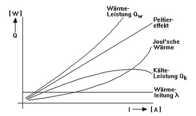
The effects counteracting the cooling of the peltier element lead to a maximum in cooling power after which an increase in electrical current leads to more extra heat being produced than the peltier element can compensate through its cooling effect. As the third term from above suggests, a larger temperature difference between the two sides of the peltier lowers its efficiency. Keeping the temperature difference low leads to the exact opposite respectively. This effect can be levered by adding/improving heatsinking on the warm side to keep it more cool leading to a lower temperature difference and thus higher efficiency.
Warm side
\( Q_{w} \): Thermal Power dissipated on warm side of peltier element [\(W\)]
\( T_{w} \): Temperature of warm side of peltier element [\(K\)]
\[ Q_{w} = T_{w} \cdot \alpha_{Elem} \cdot I + \frac{I^{2} \cdot R_{Elem}}{2} - \lambda_{Elem} \cdot \Delta T_{Elem} \]
\( T_{w} \cdot \alpha_{Elem} \cdot I \): Heating power of the peltier element
\( \frac{I^{2} \cdot R_{Elem}}{2} \): Heat produced by electrical current flowing through the peltier element, acting as an electrical resistance. Divided by two because the other half of the heat contributes to heating the cold side of the peltier element. On the warm side this effect adds to the increase in temperature
\( - \lambda_{Elem} \cdot \Delta T_{Elem} \): Heat flowing from warm side to cold side. Determined by the thermal conductivity of the peltier element and the temperature difference between its two sides. This effect counteracts the heating of the warm side as the heat flows away to the cold side.
Calculations using Mathematica
Basic concept
To simulate how the peltier elements behave under different circumstances or in different setups, a mathematica script has been written. The calculation of the thermal power is done on a recursive basis as for calculating the thermal power dissipation of the peltier element the temperature of its two sides is required. These temperatures depend on the thermal power dissipated by the peltier elements, so the script starts out with the element being room temperature and converges after some iterations on the actual values.
To calculate the temperature, it is required to know what the thermal resistances of the objects attached to either side of the peltier element are as these determine what amount of thermal power corresponds to which temperatures. Also the characteristic values of the peltier element must be known. An approximation of the air temperatures on either sides of the peltier element are also required. With these values ist is possible to calculate the thermal cooling/heating power of the peltier element depending on the electrical current flowing through it.
Motivation
First the script was used to get a feeling for what changes of the parameters affect the performance of the setup in which way. With an approximate idea of how good the components would have to perform, different arrangements of the components were tested with the script. When the components were ordered and the specifications were fixed, the performances of the different setups were calculated again, to compare the calculation to the actual performance of the setups, and to gauge how accurate the calculations are.
Parameters used for calculations
The first calculations used these parameters:
| Parameter | Value | Unit |
|---|---|---|
| Length of peltier element | 30.04 | mm |
| Width of peltier element | 30.04 | mm |
| Electrical resistance of peltier element (function of temperature T) | -2.86 + 0.02 T | Ohm |
| Thermopower of peltier element | 0.507 | V/K |
| Absolute thermal conductivity of peltier element | 0.578 | W/K |
| Specific thermal conductivity of copper | 380 | W/(K*m) |
| Specific thermal conductivity of thermal grease | 10 | W/(K*m) |
The other relevant parameters are implemented using sliders, so they can be manipulated easily.
| Object | Parameter | Value | Unit |
|---|---|---|---|
| Copper cylinder | Length | 120 | mm |
| Diameter | 60 | mm | |
| Small heatsink | Length of base | 90 | mm |
| Width of base | 100 | mm | |
| Thermal Resistance | 0.97 | K/W | |
| Large heatsink | Length of base* | 300 | mm |
| Width of base | 200 | mm | |
| Thermal Resistance* | 0.69 | K/W | |
| Approximated Temperature | Outside of box | 25.25 | °C |
| Inside box | 19.00 | °C |
* Two peltier elements are connected to the large heatsink. As they are connected to it symmetrically, only concern half of the heatsink. This leads to the length used in the calculation being half as long as the actual heatsink (300mm instead of 600mm) and the thermal resistance being double the value listed in the datasheet.
The second calculation used slightly different parameters:
The thermal conductivity of thermal grease was set to a more moderate value of 5 W/(K*m) and the parameters concerning the components bought were adjusted:
| Object | Parameter | Value | Unit |
|---|---|---|---|
| Copper cylinder | Length | 150 | mm |
| Diameter | 60 | mm | |
| Small heatsink | Length of base | 90 | mm |
| Width of base | 100 | mm | |
| Thermal Resistance | 0.7 | K/W | |
| Large heatsink | Length of base* | 300 | mm |
| Width of base | 200 | mm | |
| Thermal Resistance* | 0.22 | K/W |
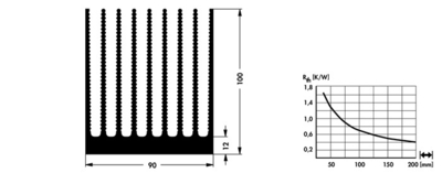
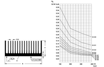
These are the datasheets for the heatsinks that were bought:
Different Setups Tested
The script was run for different setups to compare the efficiencies of them.
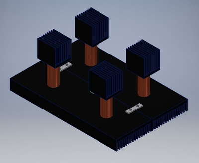
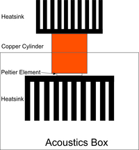 Fig. 1: Setup 1
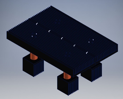
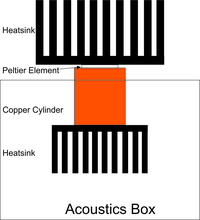 Fig. 2: Setup 2
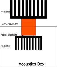 Fig. 3: Setup 3
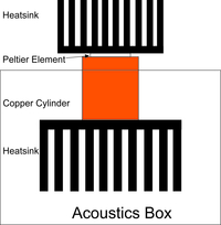 Fig. 4: Setup 4
Setup 1
In the first setup the small heatsink is on the outside of the box. The peltier and the large heatsink are inside the box. They are connected to the small heatsink on the outside using a solid copper cylinder. All connections between the individual parts are established by using thermal grease.
Setup 2
In this setup the thermal loads of the warm side and the cold side of the peltier were switched.
Setup 3
This is like setup 1 but with the position of the heatsinks switched.
Setup 4
This is like setup 2 but with the position of the heatsinks switched.
Results of first calculation
| Additional Limitations | Parameter | Setup 1 | Setup 2 | Setup 3 | Setup 4 | Unit |
|---|---|---|---|---|---|---|
| None | Electrical current leading to maximum cooling power | 1.845 | 2.245 | 2.21 | 1.865 | A |
| Maximum cooling power per peltier | 5.175 | 6.65 | 6.56 | 5.24 | W | |
| Maximum cooling power in total | 20.70 | 26.62 | 26.25 | 20.96 | W | |
| Heat produced for maximum cooling power per peltier | 18.69 | 26.09 | 25.43 | 19.03 | W | |
| Heat produced for maximum cooling power in total | 74.75 | 104.36 | 101.71 | 76.13 | W | |
| Temperature on warm side of peltier | 43.73 | 43.34 | 43.28 | 43.78 | °C | |
| Temperature on cold side of peltier | 15.4101 | 12.42 | 12.61 | 15.28 | °C | |
| Voltage per peltier under 6V | Electrical current leading to maximum cooling power | 1.845 | 1.92 | 1.9 | 1.865 | A |
| Maximum cooling power per peltier | 5.175 | 6.47 | 6.39 | 5.24 | W | |
| Maximum cooling power in total | 20.70 | 25.90 | 25.54 | 20.96 | W | |
| Heat produced for maximum cooling power per peltier | 18.69 | 20.60 | 20.25 | 19.03 | W | |
| Heat produced for maximum cooling power in total | 74.75 | 82.42 | 80.99 | 76.13 | W | |
| Temperature on warm side of peltier | 43.73 | 39.54 | 39.61 | 43.78 | °C | |
| Temperature on cold side of peltier | 15.4101 | 12.59 | 12.78 | 15.28 | °C |
The highest cooling power can be achieved by using setup 2.
The cooling power can be increased by putting the bigger heatsink on the outside of the box as well as putting the peltier outside of the box.
Results of second calculation
| Additional Limitations | Parameter | Setup 1 | Setup 2 | Setup 3 | Setup 4 | Unit |
|---|---|---|---|---|---|---|
| None | Electrical current leading to maximum cooling power | 2.02 | 3.47 | 3.00 | 2.23 | A |
| Maximum cooling power per peltier | 7.16 | 13.43 | 11.31 | 8.15 | W | |
| Maximum cooling power in total | 28.643 | 53.73 | 45.22 | 32.61 | W | |
| Heat produced for maximum cooling power per peltier | 23.07 | 55.54 | 44.04 | 27.33 | W | |
| Heat produced for maximum cooling power in total | 92.28 | 222.14 | 176.15 | 109.31 | W | |
| Temperature on warm side of peltier | 44.99 | 37.84 | 41.79 | 44.5624 | °C | |
| Temperature on cold side of peltier | 17.38 | 7.50 | 11.01 | 15.94 | °C | |
| Voltage per peltier under 6V and current under 3A | Electrical current leading to maximum cooling power | 1.87 | 1.98 | 1.94 | 1.885 | A |
| Maximum cooling power per peltier | 7.12 | 10.51 | 9.66 | 7.90 | W | |
| Maximum cooling power in total | 28.47 | 42.04 | 38.65 | 31.60 | W | |
| Heat produced for maximum cooling power per peltier | 20.68 | 24.39 | 23.33 | 21.48 | W | |
| Heat produced for maximum cooling power in total | 82.70 | 97.54 | 93.337 | 85.90 | W | |
| Temperature on warm side of peltier | 42.94 | 30.78 | 34.01 | 40.43 | °C | |
| Temperature on cold side of peltier | 17.39 | 10.01 | 12.17 | 16.03 | °C |
As above, the highest cooling power can be achieved by using setup 2 and the cooling power can be increased by putting the bigger heatsink on the outside of the box as well as putting the peltier outside of the box. Furthermore the possible output power has considerably increased for every setup by using higher performance heatsinks.
These results will have to be compared to measurements of the performances of the four different setups to find out how accurate the calculations were.
Mathematica script
Resources used
PDF "Anmerkungen zur Anwendung der Peltierelemente" by Peltron
PDF about thermoelectricity by university of darmstadt
PDF about heatsinking by Fischer Elektronik
Thermal grease datasheet
Thermal grease datasheet
Datasheet of the peltier elements used
German wikipedia article on thermal resistance
https://www.energie-lexikon.info/waermewiderstand.html
https://www.energie-lexikon.info/waermeleitfaehigkeit.html
https://www.schweizer-fn.de/stoff/wleit_metall/wleit_metall.php
https://de.wikipedia.org/wiki/Kupfer
https://de.wikipedia.org/wiki/Thermoelektrische_Spannungsreihe
https://de.wikipedia.org/wiki/Peltier-Element
Design engineering
Requirements
- Flexibilität in Positionierung der Peltierelemente nach setup 1 und 2
- Abstand Schraubverbindung in Copper Heatpipe unter Berücksichtigung von
- Abmaße Peltierelemente 30×30
- minimaler Abstand zur Materialgrenze
- Maße Kühlkörper
- Dimensionierung und Materialkalkulation der Schrauben unter Berücksichtigung von
- Zugfestigkeit
- Temperaturen die abgeführt werden durch Heatpipes und Kühlkörper - maximale Temperatur dauernd
- Ermüdung über die Zeit (speziell bei PA 6.6 Schrauben)
- Berücksichtigung der mechanischen Beanspruchung der Trennwand, aus Holz durch Lasten
- Aufgrund von asymmetrischer Anordnung der Schraubverbindung in Kühlkörpern 90×100, wurde ein Versatz in der Auflagefläche, durch Positionierung der Bohrungen in Kühlkörpern 200×500 realisiert
- Einbau zusätzlicher ITEM-Profile, die die Last des gesamten Aufbaus tragen
- Zusätzliche Sicherheit durch Aufhängung der Kühlkörper an Seilen
- wichtig: die Seile sollen im Idealfall keinerlei Frequenzen übertragen (aus diesem Grund: geeignetes Material wählen; Vermeidung einer gespannten Aufhängung) - in progress!
Mir fehlt noch, wo die Kühlkörper gekauft wurden und was die Können in Ihren Specks. Vorallem was können die im Vergleich, was Rasmus theoretisch angenommen hat.
Material and Dimensioning
Mechanical Components
Tab.1: basic idea
| number | element | diameter in mm | mass in kg |
|---|---|---|---|
| 4x | cooling element Typ:10020946 SK 507 100 SA | 90×100 | 3.6 |
| 4x | copper Heatpipes | Ø60×150 | 15.2 |
| 1x | Alu-sheet | 800×500 | 22.5 |
| 2x | cooling element | 400×500 | 36.6 |
| total mass/ kg to be held by 3xM4 | 19 (too heavy!) | ||
Tab.2: final idea with reduced mass
| number | element | diameter in mm | mass in kg | thermal resistance in K/W | technical drawings | note |
|---|---|---|---|---|---|---|
| 4x | cooling element Typ: SK 507 100 SA | 90×100 | 3.6 | 1,65 - 0,4 | kollissionsanalyse_kuehlkoerper_90x100.pdf | fischerelektronik |
| 4x | copper Heatpipes | Ø50×120 | 8.48 | - | kollisionsanalyse_heatpipes.pdf | - |
| 2x | cooling element Typ: SK 530 600 SA | 200×600 | 22 | 0,38 - 0,185 | kollissionsanalyse_kuehlkoerper_200x600.pdf kollissionsanalyse_kuehlkoerper_200x600_details.pdf | fischerelektronik |
| total mass/ kg to be held by 3xM4 | 7.62 | |||||
| 2x | fasteners of cooling elements | - | - | - | verbindungselemente.pdf | - |
| cooling system according of virtual collision analysis | kollissionsanalyse_kuehlsystem.pdf | |||||
| technical drawings for Inventor | \\afs\iqo.uni-hannover.de\user\jwolf\work\Kühlkörper | |||||
Screws
Tab.3: thermal and mechanical material characteristics
| Material | Young´s Modulus in N/mm² | DIN | maximum temperature continuous in °C | thermoconductivity in W/Km | source |
|---|---|---|---|---|---|
| Nylon PA 6.6 | 2000/ 3300 | 53456/? | 90 | 0.23 | https://www.kunststoffschraube.de/shop_content.php?coID=10 schrauben_technische_informationen_1_.pdf |
| PEEK | 3600/ 4200 | 527/527 | 260 | 0.25/ 0.27 | technisches-datenblatt-peek.pdf technisches-datenblatt-peek_4_.pdf technisches-datenblatt-peek_1_.pdf https://www.kern.de/de/technisches-datenblatt/polyetheretherketon-peek?n=1701_1 |
| steel 8.8 | 210000 | - | 15-50 | - | |
Dimensioning
Tab.4: screw joint calculations [source: kalkulation_schraubverbindung_regelgewinde.pdf ]
| Material/Diameter | tensile stress cross section (lt.Tab.) | tensile strength in N/mm² | yield strength in kg/mm² | mass in kg | note |
|---|---|---|---|---|---|
| 8.8/M4 | 8.78 | 800 | 64 | 561 | - |
| 8.8/M5 | 14.2 | 800 | 64 | 908 | - |
| 6.6/M4 | 8.78 | 600 | 36 | 316 | <hi #ff7f27>static and thermal fatigue</hi> |
| 6.6/M5 | 14.2 | 600 | 36 | 511 | <hi #ff7f27>static and thermal fatigue</hi> |
| PEEK/M4 | 8.78 | 110/116 | - | - | - |
| PEEK/M5 | 14.2 | 110/116 | - | - | - |
- Because of the low thermoconductivity of nylon and the high strength class of steel, they use nylon insulating bushes and Screw 8.8 for the first test setup [status 03/2018]
Montage Variante 1
In dieser Montage richtete man sich nach Setup 1
elektr. Bauteile
- 4x Peltierelement 30x30mm (Typ TES1-12706 ebay) max.6A/ max 14V
- werden auf beschrifteter Seite kalt mit Polung rot pos. und schwarz neg.
- Wärmeleitpaste
mech. Bauteile
- 16x Isolierbuchsen M5X11mm
- 8x M5x25mm Stahl (ISK)
- 8x M5x30mm Nylon (SS)
- 12x M4x20mm (ISK)
Montage
- die Peltierelement wurden lose zwischen dem Heatpipe und großen Kühlkörper positioniert (Setup 1)
- für bessere thermische Leitfähigkeit zwischen den Bauteilen Wärmeleitpaste verwenden
- es wurden jeweils zwei Peltierelemente in Reihe geschalten, um jede Montagevariante getrennt voneinander charakterisieren zu können
- die Schraubverbindung zw. den kleinen Kühlkörpern und den Heatpipes wurde mit M4 realisiert
Für die erste Testphase (Leistung der Peltierelemente) wurden zwei unterschiedliche Montagevarianten realisiert:
- Ein Kühlkörper wird mit Stahlschrauben und Isolierbuchsen (Rippenseitig) verschraubt, um einen thermischen/ elektrischen Kontakt zwischen den Bauteilen zu vermeiden
- der andere Kühlkörper mit Nylonschrauben/ die Isolierbuchsen werden trotzdem verwendet um sich Unterlegscheiben zu sparen
Für die Zukunft
- 16x Isolierbuchsen M5x5mm sollen verwendet werden, um einen Kontakt zw. Stahlschrauben und Peltierelementen zu vermeiden
- Aktuell sind die Stahlschrauben unisoliert
- damit die Peltierelemente sowohl Kontakt zur Kupferfläche als auch zur Kühlkörperfläche haben, wurden die Isolierbuchsen M5x5mm einseitig beschnitten; zur Vermeidung von scharfen Kanten, die das Peltierelemente beschädigen könnten wurde die Kante gefeilt
- Im Falle Installation über die Cavity:
- Überprüfe Belastbarkeit Holzwand der Akustikbox
- Akustikbox mit zusätzlichen Item-Profilen verstärken
- <hi #ff7f27>WICHTIG Für die Montage dieses Kühlsystems über die Cavity, ist die Verwendung von Nylonschrauben nicht zu empfehlen! Grund: Ermüdungserscheinungen über die Zeit</hi>
Messungen
- systematisch: elektrischer Kontakt zw. großen Kühlkörpern und Kupferzylindern nicht vorhanden
- quantitativ
- Messgerät: IR Thermometer (Typ: 62 Max+ Fluke)
Messung: Separat große Kühlkörper
Die Labornetzteile wurden auf max. 12V/5A und max. 20V/3A eingestellt. Jeweils zwei Peltierelemente in Reihe.
- nach ca 30 Min kl.KK/gr.KK:
- Nylonschrauben(17,5V/3A): 10,5°C/35°C
- Stahlschrauben(12V/2,2A): 13°C/31°C
- nach ca 25 Min. kl.KK/gr.KK:
- Nylonschrauben(18,8V/3A): 48°C/24,5°C
- nach ca. 120 Min. kl.KK/gr.KK:
- Stahlschrauben(12V/2A): 42°C/19,5°C
- Nylonschrauben(20V/3A): 55°C/18°C
- qualitativ
- Messgerät: IR-Kamera
Messung: Separat große Kühlkörper
Das Labornetzteil wurde auf max 24V/5A eingestellt. Alle vier Peltierelemente wurden in Reihe geschaltet. Die großen Kühlelemente wurden nicht zusammengeschraubt.
- nach ca 60 Min kl.KK/gr.KK (24V/2,8A):
- Nylonschrauben: 12,6°C/34,5°C
- Stahlschrauben: 14,3°C/33°C
Polarität geändert:
- nach ca 60 Min kl.KK/gr.KK (24V/1,9A):
- Nylonschrauben: 43°C/20°C
- Stahlschrauben: 40,5°C/21°C
- nach weiteren 30 min kl.KK/gr.KK (31V/2,5 -2,9A):
- Nylonschrauben: 48°C/19°C
- Stahlschrauben: 45°C/20°C
First Measurements
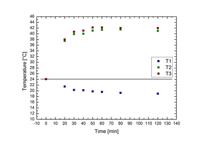
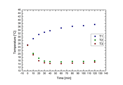
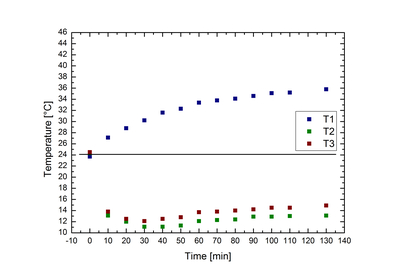
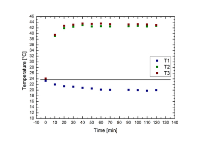
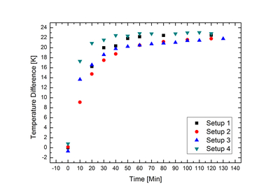
To get a feeling for the system, the temperatures of the the seperate components of different setups were measured over a span of approximately 2 hours. The components were arranged like in these setups. The peltier elements were run at 12V 5A with a lab power supply. The actual drawn current was ca. 2A. The peltier elements were connected using the correct polarity. Measurement using 62 Max+ Fluke IR temperature sensor.
T1: Temperature of the large heatsink
T2: Temperature of the left small heatsink
T3: Temperature of the right small heatsink
Setup 1
| Time [min] | T1 [°C] | T2 [°C] | T3 [°C] |
|---|---|---|---|
| 0 | 24.1 | 24.1 | 24.1 |
| 20 | 21.5 | 37.5 | 38.0 |
| 30 | 20.3 | 39.9 | 40.7 |
| 40 | 20.2 | 40.0 | 41.1 |
| 50 | 19.8 | 41.1 | 42.2 |
| 60 | 19.6 | 41.4 | 42.2 |
| 80 | 19.3 | 41.5 | 42.0 |
| 120 | 19.0 | 41.0 | 42.0 |
Setup 2
| t [min] | T1 [°C] | T2 [°C] | T3 [°C] |
|---|---|---|---|
| 0 | 25.3 | 25.1 | 25.2 |
| 10 | 29 | 20.3 | 19.5 |
| 20 | 31.5 | 17.5 | 16 |
| 30 | 32.8 | 15.8 | 14.8 |
| 40 | 33.7 | 15.5 | 14.4 |
| 60 | 35.3 | 15.3 | 14.3 |
| 80 | 36.3 | 15.6 | 14.6 |
| 100 | 36.7 | 15.6 | 14.6 |
| 120 | 37.4 | 16 | 15.2 |
Setup 3
| Time [min] | T1 [°C] | T2 [°C] | T3 [°C] |
|---|---|---|---|
| 0 | 23.7 | 24.3 | 24.5 |
| 10 | 27.1 | 13.1 | 13.8 |
| 20 | 28.8 | 12 | 12.5 |
| 30 | 30.2 | 11.1 | 12.1 |
| 40 | 31.6 | 11.1 | 12.5 |
| 50 | 32.3 | 11.3 | 12.8 |
| 60 | 33.4 | 12.1 | 13.7 |
| 70 | 33.8 | 12.3 | 13.8 |
| 80 | 34.1 | 12.4 | 14 |
| 90 | 34.6 | 12.9 | 14.2 |
| 100 | 35.1 | 12.9 | 14.5 |
| 110 | 35.2 | 13 | 14.5 |
| 130 | 35.8 | 13.1 | 14.9 |
Setup 4
| Time [min] | T1 [°C] | T2 [°C] | T3 [°C] |
|---|---|---|---|
| 0 | 23.3 | 24.1 | 24.1 |
| 10 | 22 | 39.1 | 39.5 |
| 20 | 21.4 | 41.9 | 42.7 |
| 30 | 21.2 | 42.4 | 43.1 |
| 40 | 20.8 | 43 | 43.5 |
| 50 | 20.6 | 42.5 | 43.4 |
| 60 | 20.2 | 42.6 | 43.5 |
| 70 | 20.1 | 42.5 | 43.3 |
| 90 | 20.1 | 42.6 | 43.2 |
| 100 | 20 | 42.7 | 43.3 |
| 110 | 19.8 | 42.5 | 43.2 |
| 120 | 20 | 42.7 | 43 |
Results
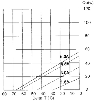
As this graph from the datasheet of the peltier elements shows, the cooling power is influenced by the temperature difference between cooling and heating side. The measurements taken, show that setups 2 and 3 have a distinctly lower temperature difference at the same electrical current, leading to the conclusion that setups 2 and 3 lead to a higher performance of the peltier elements. This supports the calculations previously made. A limiting factor is the accuracy of the measurement device, as it is an IR measuring device and is thus influenced by lighting and other effects. Also the temporal resolution could be increased. A better measuring method would be a measurement automatically logging the resistance of NTCs or other temperature sensors.
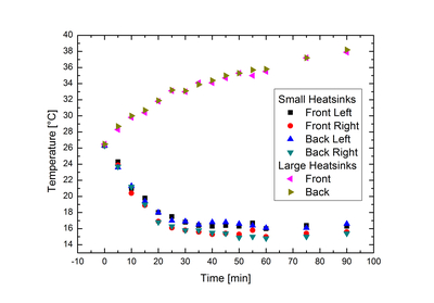
Test Measurement setup 2 with the large heatsinks connected
Setup 2 was chosen as the setup to be used and the cooling system was assembled like this with the two large heatsinks connected. A test measurement was conducted.
The lab power supply was set to drive the peltier elements at 2A. The temperature was measured with the same device as above.
| Time [min] | Temperature [°C] | |||||
| small heatsinks | large heatsinks | |||||
| front left | front right | back left | back right | front | back | |
| 0 | 26.3 | 26.3 | 26.3 | 26.3 | 26.5 | 26.5 |
| 5 | 24.3 | 23.9 | 23.6 | 23.7 | 28.3 | 28.7 |
| 10 | 21.0 | 20.4 | 21.3 | 21.2 | 29.8 | 30.0 |
| 15 | 19.8 | 18.9 | 19.4 | 19.0 | 30.4 | 30.7 |
| 20 | 18.0 | 16.9 | 18.0 | 16.8 | 31.8 | 31.9 |
| 25 | 17.5 | 16.1 | 17.0 | 16.3 | 33.1 | 33.2 |
| 30 | 16.8 | 15.8 | 16.9 | 15.8 | 33.0 | 33.1 |
| 35 | 16.4 | 15.6 | 16.5 | 15.8 | 34.1 | 33.9 |
| 40 | 16.3 | 15.3 | 16.8 | 15.5 | 34.1 | 34.4 |
| 45 | 16.4 | 15.4 | 16.8 | 15.4 | 34.7 | 35.0 |
| 50 | 16.3 | 15.3 | 16.6 | 14.9 | 35.3 | 35.3 |
| 55 | 16.7 | 15.8 | 16.4 | 15.0 | 35.0 | 35.7 |
| 60 | 16.0 | 15.0 | 16.1 | 14.8 | 35.5 | 35.8 |
| 75 | 16.4 | 15.4 | 16.1 | 15.0 | 37.2 | 37.2 |
| 90 | 16.3 | 15.6 | 16.6 | 15.4 | 37.9 | 38.2 |
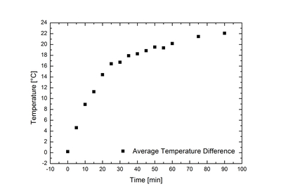
As you can see in the first graph, there is a temperature difference between the two small heatsinks on the left and the two on the right. This is probably a systematic measurement error as the temperature difference stays similar throughout most of the measurement.
The results are comparable to the measurements above and it doesn't seem like any new effects were introduced by connecting the two large heatsinks.
Further Setup
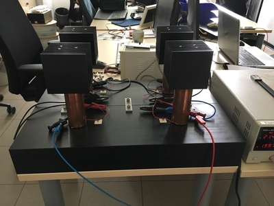
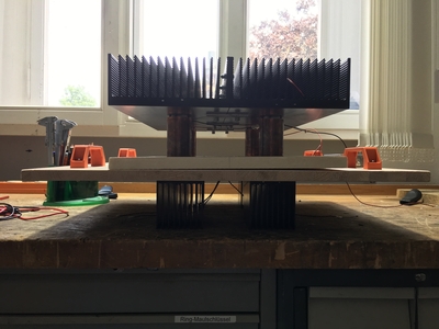
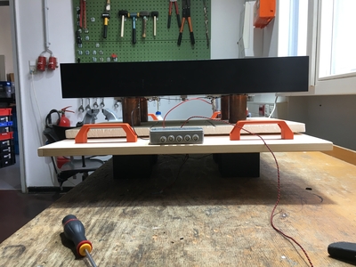
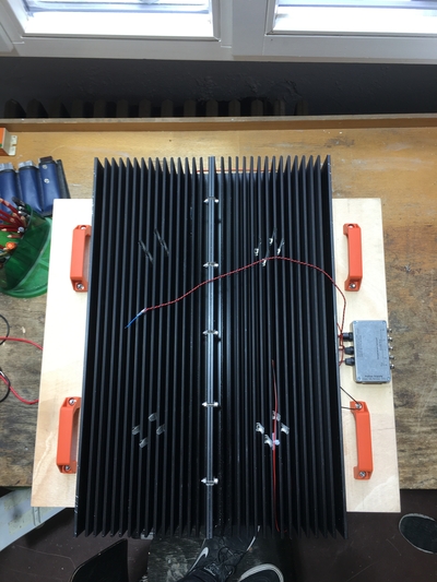
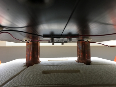
The cooling setup will be mounted on the acoustics box on a wooden board. Holes were drilled into the board for the copper cylinders and Handles added onto the board for easier transportation of the cooling system. Between the board and the large heatsinks there is a styrofoam layer insulating the holes for the copper cylinders and with cutouts for taking into account the elements mounted on the bottom of the large heatsinks.
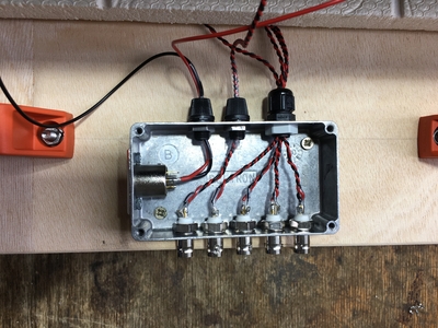
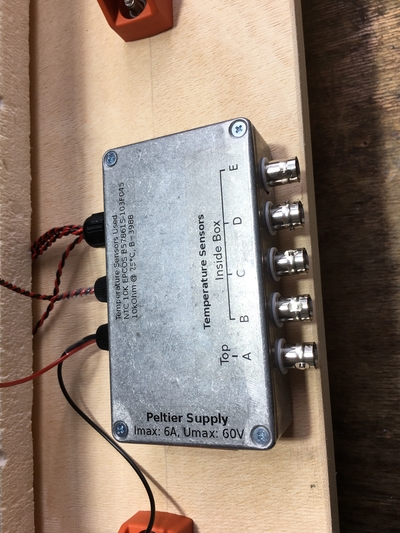
On the wooden Board a box with five BNC connectors and an XLR connector was added.The XLR connector is used for powering the peltier elements which are connected in series. The BNC connectors are for reading out NTC 10K temperature sensors, four of which are mounted on the four small heatsinks as well as one which is mounted on the large heatsinks.
Temperature Sensors used: NTC 10k EPCOS B57861S-103F045
Characteristics: 10kOhm @ 25°C, B=3988
First Boxed Tests
The Cooling system was inserted into a box to simulate the behaviour in the actual acoustics box.
To measure the approximate temperature of the air in the box, a NTC was glued to an aluminum sheet with bent edges. This sheet was layed into the box with the edges acting as spacers to reduce the influence of the box on the temperature measured.
