

meta data for this page
- en
Meerstetter Temperature Controller
Refer to the official documentation of the Meerstetter for an in-depth guide to setting up and operating the system. The manual is very rigorous and covers everything required. This article just covers the main relevant points.
- Official Website - Further information
- Datasheet - Concise data
- Manual - In depth guides
- Setup guide - Quick guide for the first setup
Currently used for these applications:
Overview
Basic Concept
The Meerstetter temperature controller is used to stabilize objects to a given temperature. It measures the temperature of the object using a thermal resistor and adjusts the object temperature accordingly by driving a heating/cooling element connected to the object.
Functionality
- Temperature stabilisation to sub mK range
- Exact control through software environment
- Easy configuration using autotuning funtion
- Custom programmable temperature ramps
- Temperature monitoring and data logging
- Programmable multi purpose pins for different applications
Hardware

X1: General connections
- power supply
- multi purpose pins
- serial connection
X2: Connections for temperature measurement and control
- peltier element/heating foil etc.
- temperature measurement
X3: USB for connection to PC
Software
Meerstetter provides a software for their temperature controller. This software is used to set up and monitor the temperature controller. It also provides a option for data logging. The newest version can be downloaded in the software section of the Official Website.
Basic Setup
If you are setting up a Meerstetter temperature controller for the first time, refer to the official setup guide. It takes you through all main steps and introduces you to the service software. The Manual also covers this topic extensively. Refer to chapter 2.
Power supply
The Meerstetter can operate in a voltage range of 5-24V DC at a maximum current of 4A. Connect the pins VIN and GND on X1 to a suitable lab power supply to power the meerstetter. The current setup for the 1560 nm rio laser diode runs at 18V.
Peltier Element/Heating Foil
The Meerstetter can run with a peltier element as well as a resistive heating element like a heating foil. The peltier element/resistive heater is connected to the pins OUT+ and OUT-. To use it correctly, you must configure the meerstetter accordingly using the service software.
Temperature Sensor

See page 4 of the Datasheet.
Object Temperature
The Meerstetter can do two-wire as well as four-wire measurement. For this the pins OBJ T° IA, OBJ T° IB, OBJ T° UA and OBJ T° UB on X2 are used. UA and UB for two wire, all four for four wire. Compatible temperature sensors are NTC, PT100 and PT1000.
When doing 2-wire measuring, these two jumpers on the back of the PCB have to be connected using solder, otherwise the TEC can't measure correctly and outputs an error. When using 4-wire this isn't necessary.

Sink Temperature
The Meerstetter can also monitor the temperature of itself. This is optional. The temperature sensor is connected to SINK T° A and SINK T° B on X2. For this an NTC is used.
Software
The newest version can be downloaded in the software section of the Official Website. Refer to the documentation given there to get started. If you want to look something up, refer to the Manual
Further Options
Status LEDs
To add a status LED to the Meerstetter, you can follow this step-by-step guide:
- connect its anode to any of the pins labelled “RES” using a resistor
- connect its cathode to GND
- connect the Meerstetter to your PC via a mini-USB B cable
- connect a power supply
- !</color> ensure the Meerstetter is connected to a load, otherwise it might be damaged * open the Meerstetter control software * make sure the Meerstetter is connected correctly and it says “ready” or “running” in the bottom left corner * type in “expert” at the bottom control panel and click the button labeled “login” * this makes the “Expert” tab show up at the top of the window * click on the tab labelled “Expert” * on the right side of the panel there are multiple selection fields labelled “RES1” to “RES8” * select the option you want to choose from the drop down menu corresponding to the pin the LED is connected to * !!! Information on what these options exactly mean can be found on pages 47 and 48 of the manual * write the settings to the Meerstetter using the button in the bottom right corner ==== Output Filter ==== As discussed as in this Email from Klaus Zipfel to the Meerstetter engineering department, the output of the Meerstetter is not perfectly smooth. To stabilise the output current, this filter was designed.
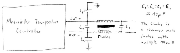 The capacitors used were the big red foil capacitors by Wima with a capacitance of ca. 10µF. The choke is a common mode choke with multiple tens of mH.
