meta data for this page
- en
This is an old revision of the document!
Temperature Controller
The temperature controller used for regulating and stabilizing the temperature of the laser diode is a Meerstetter TEC-1091-NTC56k-Pinheader - IQWiki entry
Current Setup - Rack Mount
Old setup - in a Box
Overview
- The subD9 connector is used to connect the Meerstetter to the Thorlabs mount for the laser diode and is configured specially for that purpose.
- The XLR socket is used to connect the Meerstetter to a power supply.
- The Mini-USB socket is used to connect the Meerstetter to a PC for configuration and data logging.
There is also a status LED connected to the Meerstetter. If the LED is constantly on, the wanted temperature is reached. A blinking LED means that the system is currently ramping towards the wanted temperature and if the led is off, there is an error or the Meerstetter is currently turned off.
Power Supply
The voltage range with which the Meerstetter can be powered is 5-24V DC, currently it is driven with 18V DC. The power supply should be capable of delivering 4A. Always use a seperate power supply for powering the Meerstetter.
Connections within the Case
Current Connections
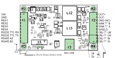
Currently the connections are as shown in the table below:
| Socket | Pin Name | Connected To | Explanation |
|---|---|---|---|
| X1 | VIN | XLR Plus | connections for the power supply |
| GND | XLR GND | ||
| RES4 | LED Anode | status LED | |
| X2 | OUT + | SUB D Pin 4 | TEC (+) |
| OUT - | SUB D Pin 5 | TEC (-) | |
| OBJ T° UA | SUB D Pin 3 | NTC (-) | |
| OBJ T° UB | SUB D Pin 2 | NTC (+) | |
| Shielding | SUB D Pin 9 | GND for shield of cable |
Different connectors were used for X1 and X2:
PSK for X1
JAE for X2
Previous Connections
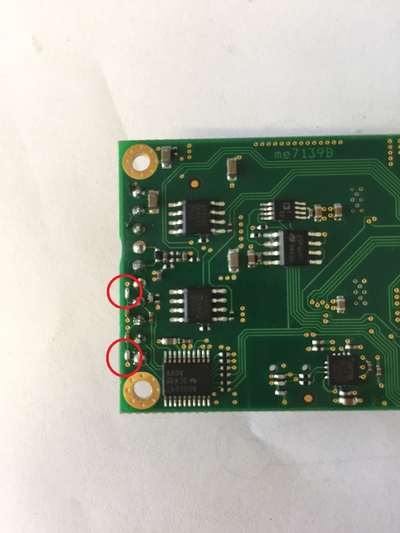
These were the previous connections. Differing connections were marked yellow.
| Socket | Pin Name | Connected to | |
|---|---|---|---|
| X1 | VIN | XLR Plus | connections for the power supply |
| GND | XLR GND | ||
| RES4 | LED Anode | status LED | |
| X2 | OUT + | SUB D Pin 4 | TEC (+) |
| OUT - | SUB D Pin 5 | TEC (-) | |
| <hi #fff200>OBJ T° IB</hi> | SUB D Pin 3 | NTC (-) | |
| <hi #fff200>OBJ T° IA</hi> | SUB D Pin 2 | NTC (+) | |
| <hi #fff200>OBJ T° UB</hi> | SUB D Pin 9 | GND for shield of cable |
Status LED
Current Setup
An extra LED is installed at the “RES4”-Pin at the X1 side with a 2,4 kΩ resistor and connected to GND.

The Meerstetter is currently set up to control the LED like this:
| LED | Meaning |
|---|---|
| constanly on | target temperature is reached |
| blinking | ramping towards target temperature |
| off | error/Meerstetter is off |
To add another status LED to the Meerstetter, you can follow this step-by-step guide


