meta data for this page
- en
This is an old revision of the document!
Seismometer Cable and Box
To connect the 14-pin output of the Titan Accelerometer you would either have to buy the proprietary cable with it's connectors and analyzer from Nanometrics or use the box and cable described here.
Schematics Used
Titan User Guide [Page 51 is important]
Cable
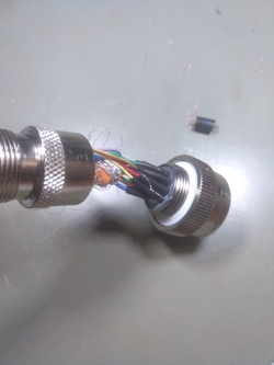
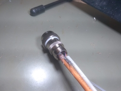
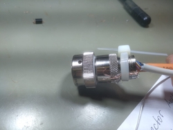
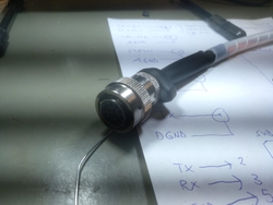
For the connecting cable between the 14-pin connector and the box we used a CAT network-cable (<fc #ffa500>orange</fc>) connected via SubD-15 and a standardized SubD-9 cable (<fc #c0c0c0>grey</fc>) with it's connector. The wires are split up into two different cables to ensure that the X-, Y- and Z-axis signals are completely shielded, hence the CAT network-cable. The analog ground signal is also fed through the shielded network cable. All the other wires go through the SubD-9 cable.
14-Pin Side
SubD-15 Side - XYZ Connect
| Pin No. | 1 | 2 | 3 | 4 | 5 | 6 | 7 | 8 | 9 | 10 | 11 | 12 | 13 | 14 | 15 |
|---|---|---|---|---|---|---|---|---|---|---|---|---|---|---|---|
| Name | +X | free | free | +Y | free | free | +Z | AGND | -X | free | free | -Y | free | free | -Z |
| Function | positive X axis output | none | none | positive Y axis output | none | none | positive Z axis output | analog ground | negative X axis output | none | none | negative Y axis output | none | none | negative Z axis output |
| Color | <fc #6495ed>blue</fc> | none | none | <fc #ffa500>orange</fc> | none | none | <fc #008000>green</fc> | <fc #800000>brown</fc> | white with <fc #6495ed>blue stripe</fc> | none | none | white with <fc #ffa500>orange stripe</fc> | none | none | white with <fc #008000>green stripe</fc> |
SubD-9 Side - Signal Connect
| Pin No. | 1 | 2 | 3 | 4 | 5 | 6 | 7 | 8 | 9 |
|---|---|---|---|---|---|---|---|---|---|
| Name | +PWR | TX | RX | free | DGND | -PWR | CAL_SIG | STATUS | free |
| Function | positve power input | serial RS-232 transmit | serial RS-232 receive input | none | digital ground | negative power in | calibration signal input | state-of-health output | none |
| Color | black | <fc #800000>brown</fc> | <fc #ff0000>red</fc> | none | <fc #ffff00>yellow</fc> | <fc #008000>green</fc> | <fc #6495ed>blue</fc> | <fc #9400d3>purple</fc> | none |
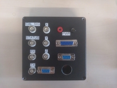
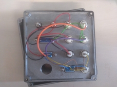
Box
SubD-9 and SubD-15 Link
The two cables coming from the seismometer have to be plugged into the corresponding [XYZ Connect] and [Signal Connect].
BNC
The BNC connectors are directly chained to the corresponding output pins of the connected seismometer. Here is a detailed layout for that:
| Description | CAL_SIG | STATUS | RX | TX | X | Y | Z |
|---|---|---|---|---|---|---|---|
| Inner Connector | CAL_SIG | STATUS | RX | TX | +X | +Y | +Z |
| Outer Ring | AGND | AGND | DGND | DGND | -X | -Y | -Z |
