

meta data for this page
Translations of this page:
- en
This is an old revision of the document!
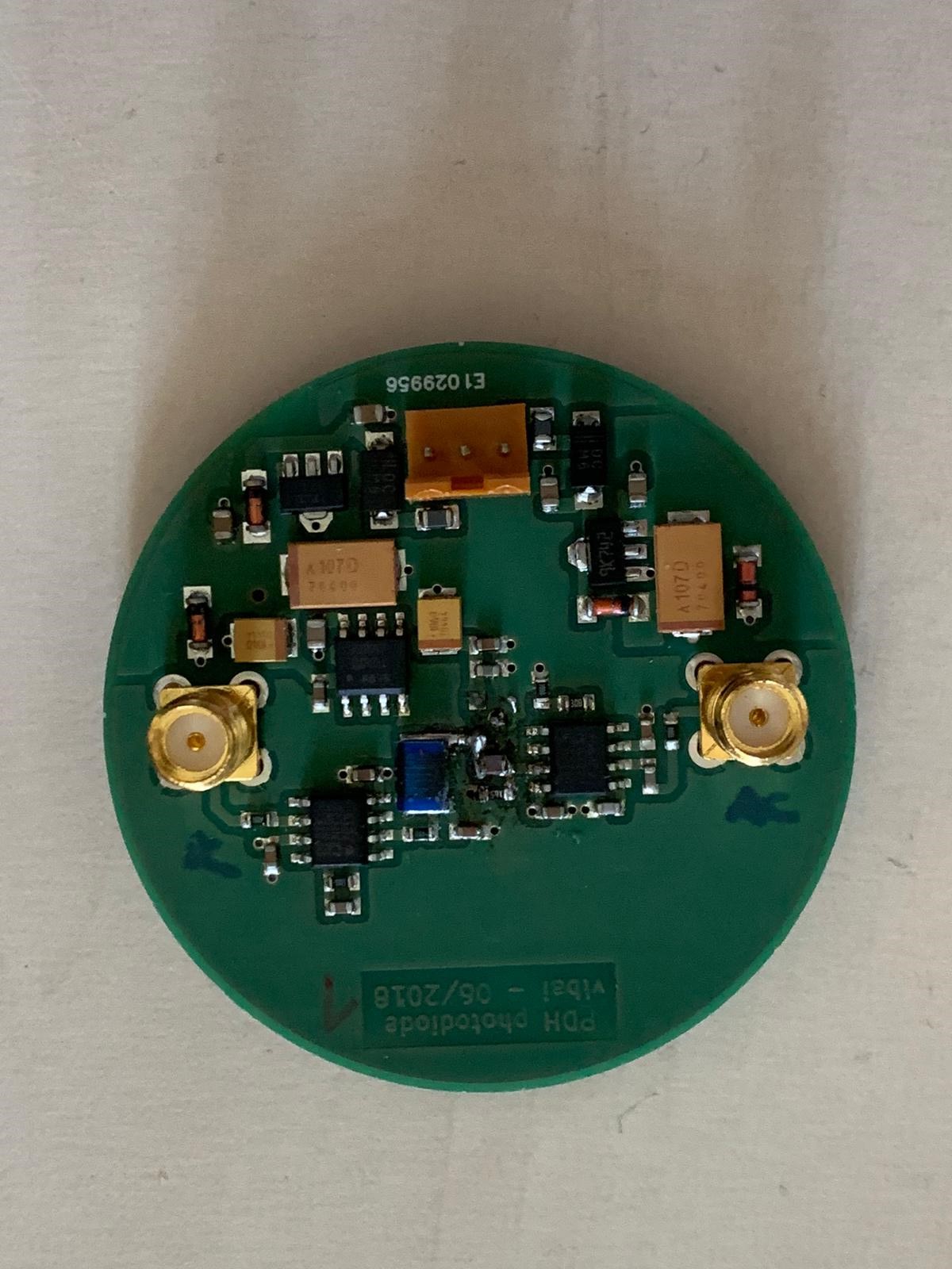
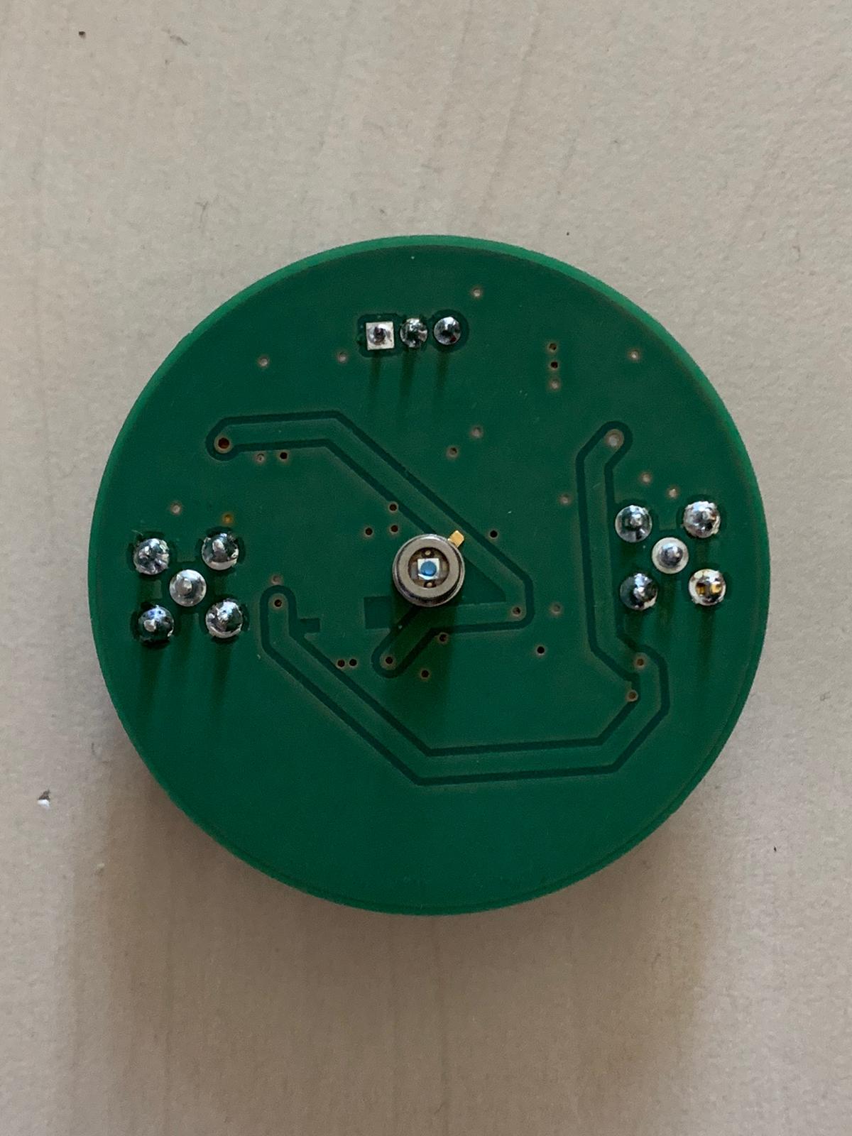
Photodiode Étienne
These photodiodes were developed by Étienne in cooperation with the AEI and altered to peak at about 16.2MHz.
Schematics Used
Notable Changes Made
To achieve a peak at around 16.2MHz, components had to be changed.
Changed components:
| Schematic Component | Used Component | |
|---|---|---|
| L1 | 6u8 | 6u8 |
| C3 | 6p | 2 x 4.7p |
| R2 | 40.2R | 40.2R |
| Changed only for the 3rd and 4th build | ||
| U5 | AD587 | LT1236A-10 |
| C19 | 1u | none |
- For Coil L1 the part 1812CS-682XJLC (or at least a part with the same form factor) has to be used
- C3 influences at which frequency the peak will be
- Instead of the AD587, LT1236A-10 can be used
- When doing this, the C19 component must not be soldered.
- C19 connects pin 8 of U5 to ground. Pin 8 is not in use in LT1236A-10.
Using The Photodiode
- The photodiode requires a power input of +/- 15V
- AC Output: right SMA connector
- DC Output: left SMA connector
- When using a spectrum-analyzer (e.g. RIGOL DSA815) in combination with the ROHDE&SCHWARZ signal-generator, a 50Ω terminator must be used, too
Measured Data
The traces of the amplitude and phase were measured.
The results:
| Diode | Resonance frequency [MHz] | Peak to 15MHz Ratio [dB] | P14R [dB] | P17R [dB] | P18R [dB] | FWHM with Gauß-Fit [kHz] | Phase #1 | Comment |
|---|---|---|---|---|---|---|---|---|
| 1 | 16.11 [+/- 0.015] | 8.65 | 13.71 | 6.99 | 12.44 | 271.75 | ||
| 2 | 16.14 [+/- 0.01] | 8.92 | 13.46 | 6.53 | 11.34 | 270.98 | ||
| 3 | 16.13 [+/- 0.01] | 9.17 | 14.75 | 6.66 | 12.13 | 271.45 | ||
| 4 | 16.16 [+/- 0.01] | 9.39 | 14.81 | 6.5 | 12.09 | 269.72 |
#1 <color #ff00ff>Was bedeutet P17 etc?</fc> #2 <color #00ff00>Peak to 17MHz Ratio [Name sollte besser noch geändert werden]</fc>
- X = MAx dazu Y Wert = Peak hight over ..
- <color #ff0000>Es feht der Fehler von der Linienbreite und des Max Peaks</fc>
- Höhe des Resonanz-Peaks über Rauschen
![FWHM [Diode 1]: 271750.86662876786Hz](/lib/exe/detail.php?id=groups%3Amg%3Aprivate%3Aresonatoren%3Aphotodiodeetienne%3Astart&media=groups:mg:private:resonatoren:photodiodeetienne:fit1.png "FWHM [Diode 1]: 271750.86662876786Hz")
![FWHM [Diode 2]: 270984.2391765082Hz](/lib/exe/detail.php?id=groups%3Amg%3Aprivate%3Aresonatoren%3Aphotodiodeetienne%3Astart&media=groups:mg:private:resonatoren:photodiodeetienne:fit2.png "FWHM [Diode 2]: 270984.2391765082Hz")
![FWHM [Diode 3]: 271450.8282159102Hz](/lib/exe/detail.php?id=groups%3Amg%3Aprivate%3Aresonatoren%3Aphotodiodeetienne%3Astart&media=groups:mg:private:resonatoren:photodiodeetienne:fit3.png "FWHM [Diode 3]: 271450.8282159102Hz")
![FWHM [Diode 4]: 269724.22527546244Hz](/lib/exe/detail.php?id=groups%3Amg%3Aprivate%3Aresonatoren%3Aphotodiodeetienne%3Astart&media=groups:mg:private:resonatoren:photodiodeetienne:fit4.png "FWHM [Diode 4]: 269724.22527546244Hz")
Wechselwirkung (WW) EOM und PD Nr.4
Spektrometer Rhode&Schwarz RBW: 100Hz VBW: 10Hz SWT: 30s Ref: 0dBm Att: 10dB
