Table of Contents
Vakuum System
Das Vakuumsystem besteht aus einer Quellen- und einer Hauptkammer. Erstere bildet ein DN63 CF T-StÄuck mit drei zusätzlich angebrachten DN40 Flanschen, an dessen Ende der Quellenaufbau mit einem Wellbalg befestigt ist. Gepumpt wird dieser Abschnitt mit einer Turbomolekular Pumpe TMU 071 P der Firma Pfeiffer mit einem nominellen Saugvermögen von 60 l/s. Die Pumpe ist bis zu einem Enddruck von 5 x 10^-10 mbar spezifiert, unterhalb dessen rückwartsgerichtete Strömungen eine Rolle spielen. Der Druck wird von einem HV-Messgerät von Athmosphärendruck bis 5 x 10^-9 mbar angezeigt. Bei ausgeschalteter Quelle befindet er sich unterhalb des messbaren Anzeigebereichs. Während des Experimentbetriebs steigt der Druck in der Quellenkammer auf Äuber 5 x 10^-9 mbar. Um zu gewährleisten, dass das Vakuum in der Hauptkammer nicht von der ausgasenden heißen Quelle beeinträchtigt wird, befindet sich zwischen beiden Kammern eine Blende mit einem freiem Öffnungsdurchmesser von 5 mm. Unterhalb des Tisches, etwa 67 cm unter Kammermitte, befindet sich eine Turbomolekularpumpe TMU 260 der Fa. Pfeiffer. Mit einer Saugleistung von 200 l/s pumpt sie das Kammervolumen über ein Verbindungsrohr von 100 mm Durchmesser. Der spezifierte Enddruck dieser Pumpe liegt unter 5 x 10^-11 mbar.
Um zusätzlich eine hohe Saugleistung für Wasserstoff zu gewährleisten, wird eine Ionengetterpumpe, eine StarCell VacIon 150 der Fa. Varian, mit einer nominellen Saugleistung von 120 l/s und 254 l/s für H2 mitverwendet. Eine Kaltkatoden-Messröhre von Balzer zeigt den Druck in der Hauptkammer von 5 x 10^-3 bis 10^-11 mbar an. Ohne Ausheizen wurde innerhalb weniger Wochen ein Druck von 4 x 10^-9 mbar erreicht. Die Empfindlichkeit der Messröhre für Magnesium liegt noch über der spezifierten Sensitivität von Argon, welche mit P0 = 0,8 x Pread angegeben wird. Das heißt, der angezeigte Wert für den Magnesium Hintergrunddampfdruck liegt über dem wahren Wert. Während des MOT-Betriebs wird ein Anstieg von wenigen 10^-10 mbar beobachtet.
How to open or pump down the Vacuum
The Instruction is on AFS in the Magnesium Document folder, also on the wall next to the vacumm controler.
| Short instruction: | ||
|---|---|---|
| Switch off the oven: Den Ofen ausschalten | 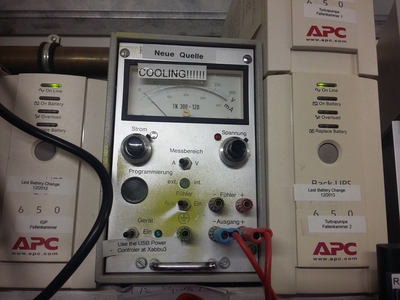 |
|
| 1. Connect protectiv gas (e.g. nitrogen) with low pressure (< 1 bar) to the vent valve of the small turbo pump and 2. connect plug to small turbo pump for ventilation at „Vent“. Avoid overpressure in the chamber at any time: Schutzgas (z.B. trockener Stickstoff, keine Edelgase) an Belüftungsventil der kleinen Turbopumpe anschließen (geringer Druck < 1 bar). Überdruck in der Vakuumkammer vermeiden. Belüftungsventil-stecker an kleine Turbopumpe anschließen („Vent“) | 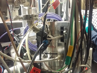 |
|
| Switch off the ion getter pump: According to Manual: Select LOCAL mode, briefly pressing the “MODE” key until LOCAL is shown on the display. Hold down the HV ON/OFF button while pressing the HV-x button where x is the number of the channel to be switched on/off. In case this does not work, or for any other issues, turning off the whole unit also works. Ionengetterpumpe ausschalten | 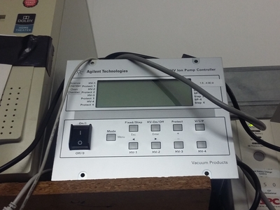 |
|
| Close valve (under the table) between the main chamber and the big turbo pump: Hochvakuumventil zwischen Hauptkammer und großer Turbopumpe schließen (unter dem Tisch) |  |  |
| Close both pneumatic valve between turbopump and prevacuum by taking out the plug from the wall near „Notaus“ at the door (it's connected to the orange switch). This closes both the pneumatic valves between the turbo pumps of the oven chamber and science chamber and their respective pre-vacuum. Make sure both valves are closed. The valve for the science chamber turbo pump is under the table. Beide pneumatischen Magnetventile zwischen den Turbopumpen und dem Vorvakuum schließen, indem der Netzstecker nahe dem Notaus an der Tür aus der Steckdose gezogen wird (in dem orangenem Schalter) | 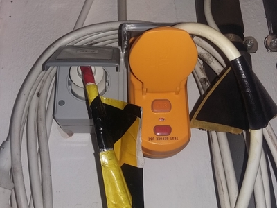 | 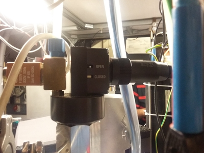 |
| Close the (yellow) hand valve at the small turbo pump: Handventil (gelb) an der Vorvakuumseite der kleinen Turbopumpe schließen | 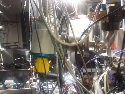 |
|
| Switch off cold cathode measuring instrument: Kaltkathoden-Messgerät (Hauptkammer) ausschalten (nicht für Druck > 10-3) mbar geeignet |  |
|
| Switch off both turbo pumps: Beide Turbopumpen abschalten | 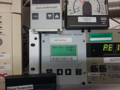 | 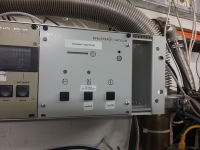 |
| Wait until turbo pumps stop rotating: glove must be filled, but without pressure. Therefore actively maintain the bypass at the gas bottle carefuly: Warten, bis die Turbopumpen zum Stillstand gekommen sind (etwa ab halber Drehzahl wird automatisch belüftet). Der Handschuh sollte stets, ohne Druck, gefüllt sein. Dafür den Fluss an der Gasflasche regulieren |  |
|
| The pressure readout at the oven will be incorrect for pressure > 1 mBar. Ventilation is finished as soon as the big turbo pump drops (bellows becomes visible): Druckanzeige an der Quellenkammmer zeigt für p > 1 mbar nicht korrekten Druck an. Belüftung ist (weitgehend) abgeschlossen, wenn die große Turbopumpe absinkt (Wellbalg wird sichtbar) | ||
We opened the Chamber on:
- 2017/10/12 Cleaned Viewports
- 2015/12/17 Changed: Lattice Viewports from vacom, Zeeman Viewport, PMT viewport
- 2015/12/23 Changed: Lattice viewports are now indium sealed again
How to evacuate the vacuum chamber
- Beforeyou close the vaccum chamber, disconnect the protective gas and the cable of the vent valve, to avoid overpressure in the chamber.
- Chack if all Viewports are assembled.
- Open (only!) the pneumatic magnetic valve of the small Turbo pump. Disconnect the plug for the pneumatic magnetic valve of the big turbo pump at the power extension board, which is located on top of the flowbox. After doing so plug in the yellow plug near the door and press 'reset'.
- Gently open the yellow hand valve at the small Turbo pump. This will pump down the chamber to the pre-vacuum level. Opening the valve will worse the pre-vacuum. Don't let the needle hit the end of the scale at the measuring device for the pre-vacuum.
- Wait until the pre-vacuum reach <10^1 mbar.
- Open the pneumatic magnetic valve at the big Turbo pump.
- Turn on both Turbo pumps and wait untill both have reached nominal speed.
- Open the valve under the table of the big Turbo pump by connecting the plug at the power extension board.
- Switch on the cold-cathod measuring device when the pressure in the main chamber is below 10^-3 mbar.
- Turn on the IGP when the pressure has reached 10^-6 mbar. Initially this will cause the pressure to rise again.
How to refill magnesium in the oven
- For opening the oven, at least two people are required.
- The Oven is attached to the chamber with a CF 63 flange. So keep a fresh CF63 copper gasket ready for replacement.
- Pump down the vacuuum chamber following the same procedure as above.
- Open the CF 63 flange connecting oven to the vacuum chamber.
- Oven is extended lengthwise into the vacuum chamber. Gently pull out the tube without hitting the walls of the chamber.
- The oven nozzle is connected in the end of the tube with a nut. Open this nut to take out the nozzle.
- Clean the nozzle as well as the inside of the oven with acetone. Make sure that acetone is fresh and does not contain any water.
- Also clean any other tools (spoons etc) that you will use to pour magnesium flakes into the oven.
- Now fill the oven to the top and again fix back the nut with the nozzle on it.
- Reconnect the oven flange to the vacuum chamber with a fresh copper gasket. Make sure that the vent gas is turned off before fixing the screws to avoid overpressure in the chamber.


Heating the pumps (usefull for low 10^-9 pressures and below and after opening the vacuum)
After opening the vacuum and pumping down again it might be necessary to heat the IGP and turbopump to reach pressures in the low 10^-9 range and below. IGP
- Install platinum thermistor on the north side of the IGP.
- Wrap three layers of aluminium foil around the (turned on) IGP.
- Slightly increase the temperature of the IGP with a “wechselstrom steller”. Go for max 3°C/min (best is 1°C/min)
- Heat the IGP (with installed magnets) to min. 130°C to 180°C (never more than 220°C). The pressure will rise up to 10^-6
- It can happen that smoke and a smell comes out of the IGP. That seems to be normal.
- Bake the IGP up to 24h (but turn off when you go home and bake the other day).
Big TurboPump
- Install platinum thermistor on the heating ring of the turbopump and wrap around aluminum foil.
- Turn on the water cooling (chiller)
- Press the “Heat” button on the turbopump controller. The temperature should never exceed 120°C
CF sealings
CF sealings are pretty easy to use. Just make sure that the flanges are clean (use acetone) and the cutting-edge of either flange is not damaged (aka scratches). You need
- New annealed copper rings (“vakuumgeglüht”)
How to seal
- Clean the surfaces of both flanges with acetone. Make sure that the cutting-edge is not damaged (no scratches)
- Clean the copper ring on both sides with acetone
- Put on the copper ring on one flange and bring both flanges in contact.
- Now install and slightly fix the screws. Always use a washer and use lubrication on the screws and threadings
- Now fix the screws in a crossed way and go round.
- In the end fix all screws with the same torque.
How to remove the seal
- Simply unscrew the screws and remove the flange and copper rings.
- If the copper ring is stuck with one flange (because it might have been fixed too tight), gently try to pull it out. Do not try to leaver it against the flange (this can destroy the cutting edge).
- If this did not help, use liquid nitrogen and try to pull it again.
Indium sealings
Indium sealed windows have the advantage that the window is not distorted by any pressure on them and you can in principle save space at the chamber. Furthermore they are UHV compatible. For best results, prepare the sealings in a dust-free environment e.g. in a clean room. Otherwise it could happen that removing the reatinment rings results in leaks due to residual dust particles
How to seal
You need
- Clean indium-wire preparation surface (e.g. on aluminum foil)
- Clean surface and flat surface (no scratches!) to press the window on
- Clean and flat window (one single dust particle can make the sealing fail)
- A stencil (optional but recommended) with half the diameter of the sealing surface to put the wire around.
- Newtonmeter/torque wrench (0 - 200 cNm)
- Retainment ring and teflong ring.
- Indium wire 0.5 mm
Cleaning a sealing-surface.
- Remove old indium with a wooden teeth-stick. Heating the surface might help
- Remove the residuals with a silver polishing pad/dull (nerv-dull/nevadul) and with the help of isopropanol and acetone.
- Remove the remaining residuals with fiberpolishing pad to further remove any residuals. The surface must be clean of any old indium
- Clean again with isopropanol and acetone.
- Clean the indium wire by gently pulling it through a lense tissue soaked with isopropanol (dont pull too much or the wire will break. Don't use acetone, since it might react with the indium)
How to seal
- Lay the cleaned indium wire on the cleaned, dust-free aluminium-foil surface which you have prepared.
- Put it around the stencil and make both ends overlap/cross a little bit.
- Put the prepared wire on the cleaned and dust-free sealing surface and press down the both crossed ends a little bit until they connect to each other and have approximately the same thickness as the original wire. Make sure, that the wire ends or the wire itself goes over the the sealing surface to the vacuum side (since indium is reactive and might interact with the magnesium).
- Put the cleaned and dust-free window on the wire, the teflon ring on the window and attach the retainment ring.
- Put in the fixing screws. Make sure you use washers for the screws. Also add a lubrication to the screws and the threading.
- Fix the screws to 35 cNm (0.35 Nm) in a crossed way and go round the screws. If you have done that, fix every screw again to 35 cNm until no screw moves anymore.
- Now repeat the following steps
- For each iterating step, slightly increase the torque by around 5-10 cNm. MAIUS successfully uses 40 cNm, 50 cNm, 55 cNm, 65 cNm, 70 cNm, 75 cNm, 80 cNm.
- Fix the screws in a crossed way and go round.
- Then, after you went fully around, try to fix every single screw again with the same torque. Do this as many times until no screw moves anymore.
- Wait 20 minutes or more even much more.
- If you pressed the indium sealing on a CF-flange (as used for the interferometer ports), install the flange on the chamber.
- Pump the chamber and tighten the screws from 70 cnM, 75 cNm to 80 Nm again as described above.
- Repeat that after some time (hours/days) over an extended timespan (many days).
- Carefully remove the retainment ring and check for leaks. You do that in reverse way as tightening the screws: Unscrew in a crossed way. If there is a leak, put on back the retainment ring and leave it attached to the window or redo the whole process to torques up to 160 cNm. But the best would be to detach the windows and repeat the whole process with super cleaned surfaces.


Removing sealed windows
Either locally heat the window or the flange, where a window might be attached to, to like 160-180 °C. This will make the indium to become liquid (T_liquid ~ 156 °C). Now you can press slightly either from the side (if attached to the chamber) or from the other side of the flange. My suggestion is to use an oven to heat flanges. When still liquid or heated, it is also easier to remove indium residuals from the flange. Be careful not to scratch the window or sealing surface, because then they will become unusable for new sealings.
Datenblätter
*Turbomolekular Pumpe TMU 071 P: tmh-tmu_071p.pdf #*In Betrieb seit XY
*Turbomolekularpumpe TMU 260: turbopump_tmh_tmu_260a.pdf #*In Betrieb seit XY
Oil change of the pre-vacuum pump
The oil has to be changed every third year approximately.
- First, close the big yellow vent at the source chamber. Second, close the pneumatik vents via the knob at the orange power outlet (close to the door) and check if both are really closed.
- CLose the black vent of the pump which is placed close to the on/off switch.
- Open the drain screw (No. 8 in manul) labed as “Ablaßschraube” in order to let the oil out. Than close the screw, let the pump run for 10 sec and open it again in order to let out the remainings. You can refill the oil Pfeiffer Oil P3 when opening the screw no. 6 until you reach a max level at the inspection window.
- Open the vents once the preassure at the pump is the same as at the source chamber.
Manual: pk115bn_part1.pdf
Last changes: nov 2018